555 Timer Ic Schematic Diagram / Schematic Circuit Diagram Monostable Latch Using 555 Timer Proteus Simulation / Monostable 555 timer circuits will automatically trigger and start a timing cycle when power is applied to the circuit.
byAdmin•
0
555 Timer Ic Schematic Diagram / Schematic Circuit Diagram Monostable Latch Using 555 Timer Proteus Simulation / Monostable 555 timer circuits will automatically trigger and start a timing cycle when power is applied to the circuit.. We have a large collection of simple and advanced projects using 555 timer ic. As discussed in the above section, the ic is in its standard monostable mode. You can for example use it to reverse the direction of a robot when it bumps into a wall. This integrated circuit can be used in a variety of ways from which the basic one is to produce accurate and stable delays in electronic circuits.additionally, it is available in 8 pin dip and 14 pin dip. One reduces the trigger sensitivity and the other will double the output pulse duration without increasing the r1 and c1 values.
When this circuit is powered it will initially stay off. Connect pin 1 of a 555 timer ic to the ground. One reduces the trigger sensitivity and the other will double the output pulse duration without increasing the r1 and c1 values. Simple 555 timer circuits & projects. In 2017, it was said over a billion 555 timers are produced.
555 Timer Astable Mode from www.ecircuitcenter.com Here, we take a look at some 555 timer circuits based on the ic. Figure 1 is the pinout and functional block diagram for the 555 timer ic. Various light actuator and relay driver circuits are also further enclosed. The 555 timer ic is an integrated circuit (chip) used in a variety of timer, delay, pulse generation, and oscillator applications. The standard 555 timer ic is made of 2 diodes. The 555 timer ic is a very cheap, popular and useful precision timing device which can act as either a simple timer to generate single pulses or long time delays, or as a relaxation oscillator producing a string of stabilised waveforms of varying duty cycles from 50 to 100%. The 555 ic timer circuit above shows a very straightforward design where the ic 555 forms the central controlling part of the circuit. 555 datasheet 555 duty cycle 555 metronome 555 reset function 555 time delay relay inverted 555 timer pulse generator.
Note this ckt diagram runs or burnt this type.
Working modes of 555 timer ic. Pin diagram of 555 ic. Now, you can easily design the different timer circuits of 1minute,5 minute,10 minute and 15 minute using 555 timer ic with ease. If you are a beginner in electronics, you should learn the basics about a 555 timer ic, before you attempt to build 555 timer circuit or a full 555 timer project. Its name is derived from three 5k ohm resistors ,connected in series used in it.the timer ic can produce required waveform accurately. Octopart is the preferred search engine for electronic parts. The standard 555 timer ic is made of 2 diodes. 555 timer ic is wired as a astable multivibrator. Basic 555 monostable multivibrator circuit. Each mode of operation indicates a circuit diagram and its output. As discussed in the above section, the ic is in its standard monostable mode. Daman shah june 5, 2021. 555 datasheet 555 duty cycle 555 metronome 555 reset function 555 time delay relay inverted 555 timer pulse generator.
If primary side copper wire size increased for example 1.5sq mm barr wire turns 40. The following example shows the 555 timer in bistable mode. In 2017, it was said over a billion 555 timers are produced. There are simple circuits for beginners and advanced engineers. To set the time duration of this circuit we have used a 550kω variable resistor.
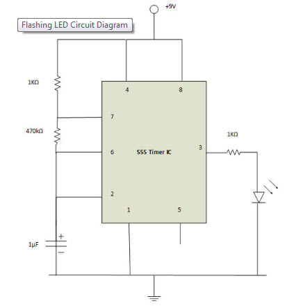
Making Of Flashing Blinking Led Circuit Diagram Using 555 Timer Ic from www.elprocus.com Let us discuss in detail about this circuit. One reduces the trigger sensitivity and the other will double the output pulse duration without increasing the r1 and c1 values. Working modes of 555 timer ic. 555 timer ic is wired as a astable multivibrator. In 2017, it was said over a billion 555 timers are produced. Adjustable on off timer(using 555 astable mode) in this circuit a timer with cyclic on off operations is designed. This circuit uses very basic components like 555 timer and 4017 counter. 555 ic timer block diagram 555 ic timer block diagram.
555 timer was first introduced by signetics corporation in 1971 as se555/ne555.
The working modes of a 555 timer are astable, bistable, and monostable. The 555 timer ic is an integral part of electronics projects. The operating voltage of this circuit is 9v. 555 timer ic is wired as a astable multivibrator. Working modes of 555 timer ic. Figure 2 shows the basic 555 timer monostable circuit. 555 timers are very popular in electronics. Derivatives provide two or four timing circuits in one package.it was commercialized in 1972 by signetics. We have seen in the last few tutorials that the 555 timer can be configured with externally connected components as multivibrators, oscillators and timers, with timing intervals ranging from a few microseconds to many hours. Daman shah june 5, 2021. Blinking led using 555 timer. This circuit uses very basic components like 555 timer and 4017 counter. As discussed in the above section, the ic is in its standard monostable mode.
As discussed in the above section, the ic is in its standard monostable mode. In 2017, it was said over a billion 555 timers are produced. Because of their availability and ease of use, the 555 astable circuit is the common source of clock signal in many synchronous circuits. 555 timer circuits (133) browse through a total of 133 555 timer circuits and projects including the timer's datasheet. Now as shown in figure, there are eight pins for a 555 timer ic namely, 1.ground.
555 Timer Ic Based Projects Circuit Diagram And Datasheet from i1.wp.com In 2017, it was said over a billion 555 timers are produced. 555 timer was first introduced by signetics corporation in 1971 as se555/ne555. Now, you can easily design the different timer circuits of 1minute,5 minute,10 minute and 15 minute using 555 timer ic with ease. 555 timer bistable example circuit. You can find the pin structure of a 555 timer ic in the circuit diagram shown above. Simple 555 timer circuits & projects. To set the time duration of this circuit we have used a 550kω variable resistor. Working modes of 555 timer ic.
As we know 555 timer ic is one of the commonly used ic among students and hobbyists.
555 ic timer block diagram 555 ic timer block diagram. Let us discuss in detail about this circuit. When this circuit is powered it will initially stay off. As discussed in the above section, the ic is in its standard monostable mode. This circuit uses very basic components like 555 timer and 4017 counter. We hope that you have got a good knowledge of 555 timer ic and different timer circuits using the same. 555 timer bistable example circuit. Figure 1 is the pinout and functional block diagram for the 555 timer ic. The working modes of a 555 timer are astable, bistable, and monostable. Here, we take a look at some 555 timer circuits based on the ic. The values of r1 and c1 determine how long the output will remain high. To set the time duration of this circuit we have used a 550kω variable resistor. Now as shown in figure, there are eight pins for a 555 timer ic namely, 1.ground.
This circuit uses very basic components like 555 timer and 4017 counter 555 timer schematic. The operating voltage of this circuit is 9v.